We generated base T = 1 tetrahedral, octahedral and icosahedral cages from the BGL17_A32 homotrimer using RPXdock20,21 to sample rotational and translational displacements of the trimer C3 axis along the threefold cage axes (Supplementary information 3). We found that for the different symmetries, different numbers of repeat units of arms (1.5, 2.5 and 3.5 repeat units for tetrahedral, octahedral and icosahedral cages, respectively) were optimal for docking of the trimers with good shape complementarity (Fig. 3a,b,e,f,i,j and see Supplementary information 3.1). The newly generated cage interfaces were designed using ProteinMPNN22, and designs for which the AF2 prediction of the arm–arm interface was less than 2.0 Å root-mean-square deviation (RMSD) from the design model were selected for experimental characterization; these comprise seven tetrahedral cages (TetT = 1-1 to TetT = 1-7; Supplementary Table 5) with 12 subunits and diameters of approximately 13 nm, 8 octahedral cages (OctT = 1-1 to OctT = 1-8; Supplementary Table 6) with 24 subunits and diameters of approximately 20 nm, and 4 icosahedral cages (IcoT = 1-1 to IcoT = 1-4; Supplementary Table 7) with 60 subunits and diameters of approximately 40 nm. All of the tetrahedral designs had peaks at the expected retention volume (Supplementary Fig. 20) on SEC, and four (TetT = 1-1, TetT = 1-2, TetT = 1-4 and TetT = 1-6) were structurally homogeneous by nsEM (Extended Data Fig. 1 and Supplementary Fig. 21), with 2D class averages and 3D-reconstructed nsEM maps (Fig. 3c and Supplementary Fig. 21) matching the design models (Fig. 3b,c). Seven of the octahedral cages had single peaks on SEC, and two (OctT = 1-2 and OctT = 1-4) showed homogenous structures matching the design models by nsEM (Fig. 3f,g and Supplementary Figs. 22 and 23). One of the icosahedral cages, IcoT = 1-1, had a single peak on SEC and was close to the design model by nsEM (Fig. 3j,k), although imperfectly formed cages were also observed (Supplementary Fig. 24).
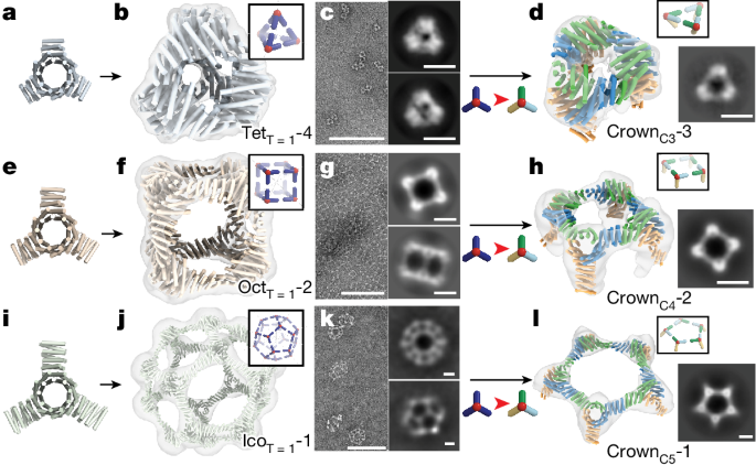
a–c,e–g,i–k, BGL17_A32 with 1.5 (a), 2.5 (e) and 3.5 (i) repeat unit arms docked into tetrahedral (TetT = 1-4; b,c), octahedral (OctT = 1-2; f,g) and icosahedral (IcoT = 1-1; j,k) T = 1 cages. Superpositions of the 3D-reconstructed nsEM map (transparent cloud) on the cage design model (colours) are shown (b,f,j). nsEM micrographs (left) and characteristic 2D class averages (right) of the cages are also displayed (c,g,k). d,h,l, C3 (crownC3-3), C4 (crownC4-2) and C5 (crownC5-1) crowns made from pseudosymmetric heterotrimers. Left, superpositions of the 3D-reconstructed nsEM map on the crown design model (ch_A (green), ch_B (blue) and ch_C (orange)). Right, 2D class averages along threefold, fourfold and fivefold symmetry axes. The diameters of the crowns are 11 nm (C3), 20 nm (C4) and 35 nm (C5). Scale bars, 100 nm (c,g,k (left)) and 10 nm (c,g,k (right),d,h,l). See Extended Data Tables 3 and 4 for the amino acid sequences of the T = 1 cages and crowns.
We next extracted C3, C4 and C5 symmetric cyclic oligomers (which we refer to as crowns because of their shape) from the structurally confirmed T = 1 cages by substituting in the structurally identical pseudosymmetric hetBGL0-18-17_A32 heterotrimer in place of the BGL17_A32 homotrimer (Fig. 1, third and fourth columns). The chain A (ch_A) and ch_B interfaces were redesigned using ProteinMPNN to interact at the crown trimer–trimer interface; this was necessary to avoid a potential off-target structure possible with the original C2 interface (Supplementary Fig. 25). The surface of the arm of ch_C, which points outwards from the crown, was redesigned to be entirely polar. This isolates the crowns as free-standing building blocks that can be used to build T = 4 cages in the next step. We selected designs for which AF2 predicted the ch_A–ch_B interface with RMSD < 2 Å and did not predict the ch_A–ch_A or ch_B–ch_B homodimer interfaces to form (Supplementary Fig. 19). We obtained genes encoding 19 sets of crowns that passed these filters (crownC3-1 to crownC3-5 for C3 crowns, crownC4-1 to crownC4-7 for C4 crowns and crownC5-1 to crownC5-7 for C5 crowns; Supplementary Tables 8–10), and the three chains for each crown were expressed separately in independent E. coli cultures. Following expression, the amount of each protein was estimated by SDS–PAGE gel densitometry, and appropriate amounts of culture were combined to achieve mixtures with stoichiometric amounts of the three chains, which were co-lysed and co-purified. By SEC, four of five C3, five of seven C4 and two of seven C5 crowns had peaks at the expected elution volumes (Supplementary Figs. 26–31) containing three distinct bands by SDS–PAGE (Supplementary Fig. 32), indicating that the complexes were heterotrimers. nsEM 2D class averages and 3D-reconstructed nsEM maps matched well with the crown design models (Fig. 3d,h,l and Extended Data Fig. 1). Thus, symmetric substructures can be extracted from larger symmetric assemblies by substituting homotrimers with pseudosymmetric heterotrimers.
In the final step of our hierarchical design approach, we designed T = 4 cages by combining the experimentally confirmed crowns with the BGL17_A32 homotrimer (Fig. 1, last column, and Supplementary information 3). The C3, C4 and C5 crowns were aligned with the threefold, fourfold and fivefold axes of tetrahedral, octahedral and icosahedral architectures, and BGL17_A32 was aligned to the remaining threefold axis. This generated assemblies in which the heterotrimer arms pointing outwards from the crowns (ch_C of heterotrimer) interact with the arms of the homotrimer (ch_ho). To find optimal docking interfaces, we used RPXdock, sampling the lengths of the interacting arms and the rotations and translations along the common axis, and designed sequences using proteinMPNN for the highest RPX scoring models for each symmetry. Designs were filtered based on the formation of the designed interface, and lack of formation of the self interfaces, in AF2 predictions (Supplementary Fig. 19). Very few initial designs for the octahedral architecture did not form predicted self interfaces; thus, to decrease the probability of self-interaction, we performed explicit negative design using proteinMPNN22 against the predicted self interfaces. We experimentally tested 14 sets of T = 4 cage designs (TetT = 4-1 to TetT = 4-5, OctT = 4-1 to OctT=4-4 and IcoT = 4-1 to IcoT = 4-5; Supplementary Tables 11–13) that passed the AF2 filters. The four components were expressed independently in different E. coli. cultures, mixed with 1:1:1:1 stoichiometry and co-lysed. The lysed samples were purified using immobilized metal affinity chromatography and SEC, and the cage structures were characterized by nsEM (Extended Data Fig. 1 and Supplementary Figs. 35–47). As described in the following paragraphs, the major species in each case was the designed T = 4 structure; we also observed minor species of smaller off-target T = 1-like cages (Supplementary Figs. 37, 42 and 45).
The T = 4 tetrahedral cage (TetT = 4-2) has a tetrapod shape (diameter of 33 nm) with the four C3 crowns pointing outwards, and the homotrimers bridging the crowns closer to the centre of the cage and facing inwards (Fig. 4a,d,g and Supplementary Fig. 36). The homotrimer–heterotrimer distance (11.5 nm) is almost twice the heterotrimer–heterotrimer distance (6.0 nm) due to the arm length difference between components (1.5 repeat units for ch_A and ch_B, and 3 repeat units for ch_C and ch_ho), and the interior volume is a tetrahedral channel 6.0 nm in width (Fig. 4d). Overall, the structure maps to a T = 4 Goldberg polyhedra with tetrahedral symmetry23, in which the hexagonal motifs between triangles are highly elongated (Fig. 4a). These structural features are evident in the nsEM map (Fig. 4d), micrographs (Fig. 4e) and 2D average classes (Fig. 4f), and the design model is closely consistent with the reconstructed nsEM map (Fig. 4g). The design model could be readily relaxed to fit the nsEM 3D map with all four components clearly within density (Supplementary Fig. 36); overall, the relaxed model matches well with the design model, with the exception of a slight twist of the overall structure resulting from curvature in the arm near the homotrimer–heterotrimer interface (Fig. 4d and Supplementary Fig. 36).
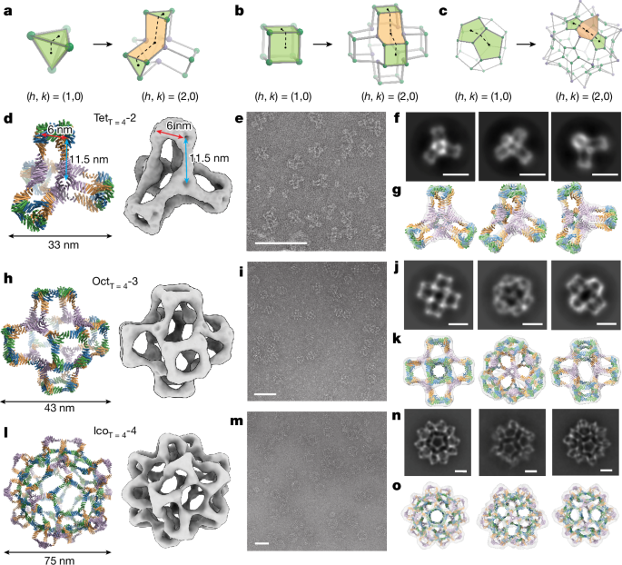
a–c, Ball-and-stick models of T = 1 (left) and T = 4 (right) cages for each symmetry, defined by the Caspar and Klug nomenclature8. d–o, Four component T = 4 tetrahedral cage with 48 subunits (d–g), octahedral cage with 96 subunits (h–k) and icosahedral cage with 240 subunits (l–o). Design models of the T = 4 cages (left) and a 3D-reconstructed nsEM map (right) are shown (d,h,l). In the design models, each chain is shown in a distinct colour (ch_A (green), ch_B (blue), ch_C (orange) and ch_ho (purple)). nsEM micrographs (e,i,m), characteristic 2D class averages of nsEM (f,j,n) and superpositions of the 3D-reconstructed nsEM map (grey density) on the cage design model (colours; g,k,o) are also displayed. Scale bars, 100 nm (e,i,m) and 20 nm (f,j,n). See Extended Data Table 5 for the amino acid sequences of the T = 4 cages.
The T = 4 octahedral cage (OctT = 4-3) has a 3D cross shape structure (diameter of 43 nm) with the original cubic shape of the T = 1 structure repeated six times and shifted away from the origin to positive and negative values of x, y and z along the three fourfold symmetry axes (Fig. 4b,h). Six C4 crowns form the outward faces of the structure along the x, y and z axes, which are connected by eight homotrimers placed in a cubic arrangement closer to the centre of the cage; as for the tetrahedral cage, the homotrimers and heterotrimers face in opposite directions (Supplementary Fig. 40). The overall architecture is that of a T = 4 Goldberg polyhedra with octahedral symmetry23, with an elongated hexagon bridging the square faces (Fig. 4b) and a 10-nm cavity in the centre. Homogeneous populations of cages are observed in nsEM micrographs (Fig. 4i), and 2D class averages along the twofold, threefold and fourfold symmetry axes are closely consistent with the design model (Fig. 4j). The nsEM 3D reconstruction is very close to the design model (Fig. 4k), but a slightly curved connection between crowns and homotrimers leading to a slight twist of the overall structure (Supplementary Fig. 40). To characterize the structure of OctT = 4-3 at higher resolution, we collected cryo-electron microscopy (cryo-EM) data and generated a 3D reconstruction, which, following refinement, resulted in a 3D cryo-EM map with 6.87 Å resolution with clear secondary structure features (Fig. 5a–d and Supplementary Fig. 51). Following relaxation via molecular dynamics24, the design model fits well into the cryo-EM map (Fig. 5e–g), with the crown and homotrimer substructures and the individual chains clearly defined (Supplementary Fig. 41). Around the fourfold symmetry axes, ch_A and ch_B of the hetBGL0-18-17_A32 heterotrimers (Fig. 5b,e, green and blue) form square motifs; the five helices in each arm in both chains are clearly evident in the cryo-EM map (Fig. 5e). BGL17_A32 homotrimers are placed along the threefold symmetry axes (Fig. 5d); the arm of each subunit has six helices and forms an interface with ch_C of the heterotrimer at the end (Fig. 5f,g, purple and orange). The slight twist of the C4 crown substructures relative to the design model arises from shifts at the homotrimer–heterotrimer interface (Supplementary Fig. 41).
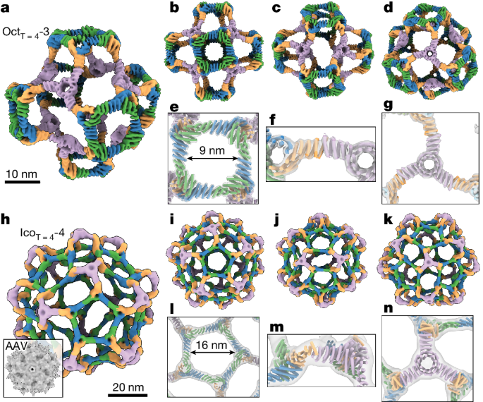
a–d, 3D cryo-EM map of OctT = 4-3 from different views. e–g, Overlay between the cryo-EM map (grey transparent) and the design model relaxed into the map (colours) for each substructure: C4 crown (e), the homotrimer–heterotrimer interface (f) and the homotrimer (g). h–k, 3D cryo-EM map of IcoT = 4-4 from different views. The inset (h) is an adeno-associated virus (AAV) capsid shown at the same scale for size comparison. l–n, Overlay between the cryo-EM map (continuous density) and the relaxed design model (colours) for each substructure: C5 crown (l), the homotrimer–heterotrimer interface (m) and the homotrimer (n). Both the cryo-EM map and the protein model are coloured by chain (ch_A (green), ch_B (blue), ch_C (orange) and ch_ho (purple)). See Extended Data Table 7 for cryo-EM data collection information.
The T = 4 icosahedral cage (IcoT = 4-4) consists of 12 C5 crowns (pentons) connected by 20 outwards-facing homotrimers (Fig. 4c,l). Largely homogeneous 75-nm-sized cages were identified by nsEM and dynamic light scattering (DLS; Fig. 4m and Supplementary Fig. 44). SDS–PAGE showed clear bands corresponding to each component, suggesting that all four chains are present (Supplementary Fig. 43). The 2D class averages (Fig. 4n) and 3D nsEM reconstructions (Fig. 4l,o) have the overall designed shape but the orientations of the C5 crowns, and homotrimers appeared inverted from the design model (Supplementary Figs. 34 and 47). We collected cryo-EM images, and 3D reconstruction and refinement of the cryo-EM data yielded a 3D cryo-EM map with 13.15 Å resolution (Fig. 5h–k and Supplementary Fig. 51), in which the holes at the centre of trimers and the orientations of trimers are clearly identified. The design model with inverted components fits well into the cryo-EM density following relaxation (Fig. 5l–n and Supplementary Fig. 48). The overall structure has the architecture of a T = 4 Goldberg polyhedron with icosahedral symmetry23, with boat-type hexagonal motifs placed between pentagons (Fig. 4c). Surrounding the fivefold symmetry axes are pentons formed from hetBGL0-18-17_A32 heterotrimers (Fig. 5h,i, green, blue and orange). The pentons are bridged by BGL17_A32 homotrimers, which form tripod-like protrusions on the threefold symmetry axis (Fig. 5h,k, purple). On the twofold axes are boat-type distorted hexagons with two homotrimers and four heterotrimers on the vertices; two of the edges are formed by interacting heterotrimer subunits, and four edges are formed by interacting homotrimer and heterotrimer subunits (Fig. 5j). The outer diameter of the IcoT = 4-4 cage is about three times larger than that of the adeno-associated virus capsid (Fig. 5h), and the inner diameter of the empty pore at the centre of the IcoT = 4-4 cage is approximately 50 nm (volume of approximately 6.55 × 10⁴ nm3), which can be used to package diverse cargos such as nucleic acids and enzymes.
We tested the thermal stability and pH tolerance of the OctT = 4-3 and IcoT = 4-4 cages using DLS (Supplementary information 4.5). The Z-average diameter (dZ) of the two cages was consistent with the expected diameters of the intact cages (approximately 80 nm for IcoT = 4-4 and approximately 50 nm for OctT = 4-3) at 25 °C (the smaller T = 1 contaminants observed by electron microscopy were not resolved by DLS probably due to the screening effect of the larger of two similarly sized particles25), was unchanged from 25–70 °C and then decreased above 75 °C (Fig. 6a,b). To test pH tolerance of the cages, we measured dZ while decreasing the pH of the buffer. The IcoT = 4-4 dZ of around 80 nm was unchanged from pH 8.0 to pH 5.3, but increased at pH 4.7, probably due to aggregation (Fig. 6c), whereas the OctT = 4-3 of approximately 50 nm was unchanged between pH 8.0 and pH 6.4, but increased at pH 5.9 or lower (Fig. 6d). Thus, the cages are quite thermostable (melting temperatures higher than 70 °C), which should facilitate their development as delivery vehicles, and undergo pH-dependent transitions at the pH sampled in the endocytic pathway, which may be exploitable for endosomal escape.
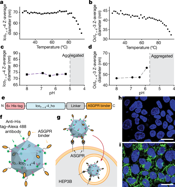
a–d, Z-average diameter of IcoT = 4-4 and OctT = 4-3 at varying temperature (a,b) and pH (c,d), measured by DLS. e, An ASGPR binding cage was generated by fusing the ch_ho chain of IcoT = 4-4 to an ASGPR-binding protein. f,g, Schematic of the ASGPR cage (f) and internalization of the cage in HEP3B cells (g). h,i, Confocal microscope images of HEP3B cells treated without (h) and with (i) the cages. Nuclei were stained with DAPI (blue), and nanocages with anti-His–Alexa-488 are shown in green. Scale bars, 30 µm (h,i).
As a first step towards exploring the use of the cages for delivery applications, we evaluated internalization by fusing one of the four components of IcoT = 4-4 (ch_ho) to a designed binder26 of asialoglycoprotein receptor (ASGPR) (Fig. 6e and Extended Data Table 6). ASGPR is an endocytic internalizing receptor that is exclusively expressed on the surface of liver cells. This receptor has been utilized for delivery of therapeutic oligonucleotides such as small interfering RNA27 and liver-specific LYTAC-mediated protein degradation26,28. Sixty ASGPR mini-binders were displayed on the outer surface of the IcoT = 4-4 cage through genetic fusion (Fig. 6f). We labelled the ASGPR cages with anti-His tag–Alexa-488 antibody (the subunits each have His tags) and incubated them with the hepatocellular carcinoma cell line HEP3B. By confocal imaging, we observed a substantial intracellular accumulation of the cage in a punctate localization pattern, probably indicating vesicle localization, whereas treatment with only anti-His–Alexa-488 antibody without the cage resulted in no intracellular signal (Fig. 6h,i). This result suggests that these large designed T = 4 cages can be internalized by cells for delivery or LYTAC applications.


